Hardware Setup
Host Interface
LimeSDR XTRX should be plugged into a Mini PCIe slot on the host device.
The host must provide a PCIe Gen2 x1 or x2 interface, and supply power via the Mini PCIe connector.
In general use case LimeSDR XTRX is connected to PCs PCIe slot via Mini PCIe adapter like LimeFEA mPCIe.
Note
Most COTS equipment with Mini PCIe slots provide only a single PCIe lane (x1), which will result in slightly reduced bandwidth.
A custom baseboard or adapter is required to use both PCIe lanes (x2), but PCIe x1 operation is sufficient for most use cases.
Note
Custom gateware is required for data transfer via the USB 2.0 interface.
Cooling
Depending on the application, host system and ambient temperature, additional cooling may be required to ensure reliable operation of the LimeSDR XTRX board. This may be in the form of airflow through the host system, or a dedicated heatsink fitted to the board.
When designing a cooling solution for a LimeSDR XTRX–based system, power dissipation should be evaluated based on the specific user configuration and use case. In general, the LimeSDR XTRX cooling solution should be designed to dissipate at least 4 W of power, providing sufficient thermal margin to ensure safe and reliable operation during peak loads.
Note
In the event of errors, instability or reduced performance, check the board temperature to ensure that it is within the specified operating range.
RF Connections
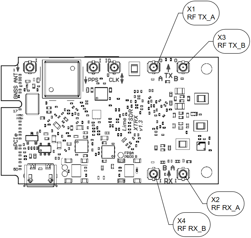
Figure 3: LimeSDR XTRX v1.3 board top with RF connector positions
Connector |
Type |
Function |
Band |
Frequency range |
|---|---|---|---|---|
X1 (Ch1), X3 (Ch2) |
U.FL |
TX ouptut |
TX low |
0.03 - 1.9 GHz |
TX high |
3.3 - 3.8 GHz |
|||
X2 (Ch1), X4 (Ch2) |
U.FL |
RX input |
RX low |
0.3 - 2.2 GHz |
RX wide |
0.7 - 2.6 GHz |
|||
RX high |
3.3 - 3.8 GHz |
Note
TX and RX bands frequency ranges are determined by matching networks. These bands frequency ranges can be changed by replacing their matching networks components.
Warning
Care should be taken when connecting external RF signals to the RX inputs, to ensure that the maximum safe input power of +10 dBm is not exceeded, as this may cause permanent damage to the device.